The Future of Cave Mapping: Laser Precision Meets Photorealism
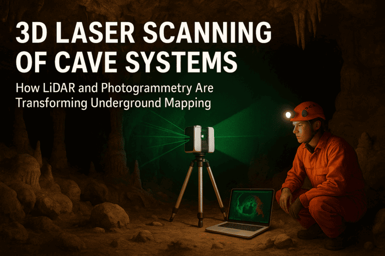
3D Laser Scanning of Cave Systems: How LiDAR and Photogrammetry Are Transforming Underground Mapping
Mapping caves used to mean wet notebooks, tape measures, and lots of guesswork. Today, laser scanners and camera arrays produce survey‐grade 3D models that capture every bend, boulder, and breakdown pile often with millimeter detail. This article explains how LiDAR and photogrammetry work underground, where each shines, how to combine them, and what this revolution means for science, conservation, engineering, and exploration.
Why map caves in 3D?
Safety & planning: Accurate models help route trips, place rigging, and plan rescues.
Science: Geometry, rock textures, speleothem volumes, sediment layers, and airflow pathways can be quantified rather than just described.
Conservation: Baseline condition models enable change detection (e.g., vandalism, visitor impact, dripstone growth).
Engineering: Mining, tunneling, and groundwater projects rely on precise void geometry and fracture networks.
Storytelling: Immersive visualizations allow the public to “visit” fragile or hazardous passages without touching them.
The two pillars LiDAR (Light Detection and Ranging)
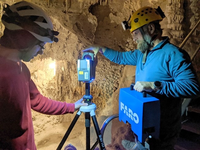
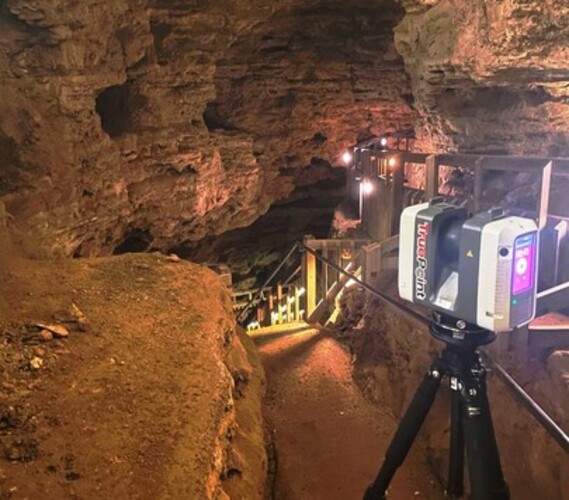
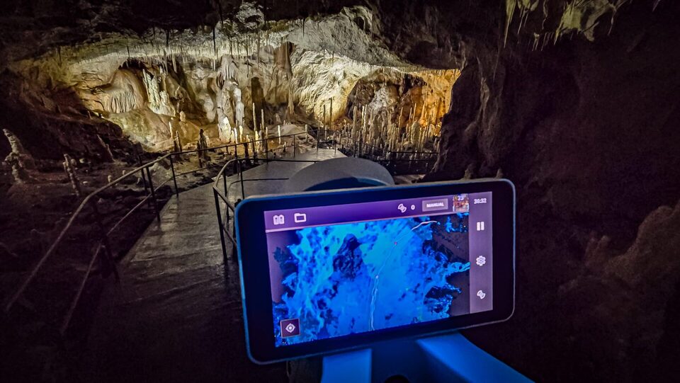
How it works: A laser emits pulses and times their return from surfaces. A rotating mirror or solid-state array sweeps the beam to capture millions of points per second.
Outputs: Dense, uniformly accurate point clouds with direct range and intensity (reflectance) values.
Strengths underground:
Works in complete darkness (self-illuminating).
Handles complex geometry and long shot distances well.
Offers predictable accuracy and low noise even on featureless surfaces.
Limitations:
Equipment can be heavier and pricier.
Shiny, wet, or highly absorbent surfaces can reduce returns.
Color is limited to intensity unless a camera is integrated.
How it works: Overlapping photos from different positions are processed to reconstruct 3D structure (Structure-from-Motion / Multi-View Stereo).
Outputs: High-resolution meshes and textured models; point clouds derived from imagery.
Strengths underground:
Captures rich color and texture (great for speleothems, paleo markings).
Lightweight cameras; flexible rigs (handheld, helmet-mounted).
Cost-effective and scalable.
Limitations:
Needs controlled lighting and heavy overlap.
Struggles with homogeneous or reflective surfaces (mud banks, pools).
Absolute scale and accuracy depend on ground control.
Typical underground workflows
Recon & plan
Identify scan stations (LiDAR) or photo paths (photogrammetry).
Establish control: targets or surveyed points tied to a cave datum or surface GNSS (via entrance tie).
Data capture
LiDAR: Set up at stations ~5–20 m apart in complex passages; denser spacing in narrow or highly occluded areas. Use checkerboard spheres/targets for registration if needed.
Photogrammetry: Shoot 70–90% overlap; move slowly; avoid hot spots and deep shadows with diffused, high-CRI LEDs. Bracket exposures for shiny or dark surfaces.
Registration & scaling
LiDAR: Register scans by targets or cloud-to-cloud alignment (ICP). Check residuals at each merge.
Photogrammetry: Solve camera poses, then fix scale with measured distances/targets; refine with bundle adjustment.
Fusion (optional but powerful)
Use LiDAR for geometry, photogrammetry for texture:
Snap the photo-derived mesh or points to the LiDAR cloud.
Bake high-res textures onto the LiDAR mesh.
Result: survey-grade geometry with photorealistic appearance.
QA/QC
Inspect overlap, check control residuals, compute point-to-point or mesh-to-mesh deviations.
Flag occlusions and low-confidence zones on a map layer.
Deliverables
Point clouds: LAS/LAZ, E57.
Meshes: OBJ/PLY/GLB.
Orthoprojections: Cave wall orthos, plan and profile views.
Metrics: Passage cross-sections, volume, clearance, slope, fracture orientations.
XR/VR tours: For interpretation and training.
Accuracy & resolution in practice
LiDAR: Ranges from ~2–10 mm at short standoff with terrestrial units; mobile SLAM units can be ~1–3 cm depending on loop closures and drift control.
Photogrammetry: Sub-centimeter detail is common with good lenses and control; absolute accuracy depends on control layout and lighting.
Ground control matters: Distributed, well-measured targets beat a single scale bar. Redundancy and loops reduce drift.
Surface challenges: Wet calcite, pools, and featureless clay benefit from cross-polarized lighting or using LiDAR to anchor geometry.
Lighting that works
Diffuse first: Soft panels or bounced light minimize specular glare.
Consistent color: High-CRI LEDs avoid weird hues on calcite and sediment.
Cross-polarization: Linear or circular polarizers on lights and lens dramatically cut reflections on wet rock.
Mind the dust: Silt in the air scatters light; pause after team movement and avoid pointing beams into the field of view.
Safety and logistics
Team roles: Scanner, light wrangler, cord/tether manager, scribe. Keep comms simple.
Power & moisture: Dry bags, silica gel, and insulated batteries; pre-warm packs near the entrance in cold caves.
Rigging: Plan for stable tripods or monopods in breakdown piles; use soft feet to avoid damaging formations.
Traceability: Label stations, photo sequences, and control IDs on waterproof tags; maintain a shot log even if devices track metadata.
Data management underground
In the field: Duplicate to two rugged SSDs after each push; verify hashes.
Processing: Keep raw imagery, clean point clouds, and final meshes in separate folders with readme files. Maintain versioned project files.
Archiving: Use open formats (E57, LAZ, OBJ) and store derived GIS layers with coordinate frames documented.
Applications that weren’t possible before
Time-lapse geomorphology: Compare models to quantify breakdown, sediment movement, speleothem growth, or flood scours.
Airflow & hydrology modeling: Use 3D geometry to simulate ventilation and flood routing.
Biodiversity niches: Measure micro-habitats (ceiling pockets, drip zones) and correlate with species observations.
Accessibility: Virtual traverses for training, education, and regulated site access decisions.
Common pitfalls (and how to avoid them)
Registration creep: Close loops and include control in multiple stations. Check residuals after every major merge.
Uneven texture: Keep lighting rigs at consistent distances/angles; avoid “headlamp hotspots.”
Gimbal lock & featureless runs: Insert textured targets or temporary markers in blank corridors (remove after).
Over-decimation: Preserve a high-resolution master; publish lighter derivatives for the web.
Metadata loss: Bake camera poses, control coordinates, and CRS into project notes and exports.
A quick start kit (field-proven)
Capture: Terrestrial LiDAR (or backpack SLAM for speed) + mirrorless camera with fast wide-angle lens (prime 20–24 mm), lens polarizer, diffused LED panels, spare batteries.
Control: Lightweight targets, stainless steel tape or laser Disto, notebooks/rite-in-rain, and a few permanent reference marks near the entrance (placed responsibly).
Processing: LiDAR registration software; photogrammetry suite (SfM/MVS); meshing/cleanup tool; GIS for profiles/orthos; a web viewer for sharing (glTF/GLB).
Ethical and conservation considerations
Touch nothing: Use existing trails; avoid formations; place removable targets.
Data sensitivity: Mask locations of sensitive features (cultural sites, rare fauna).
Attribution & access: Share models responsibly; involve land managers and local caving groups.
Minimal footprint: Light discipline, quiet operation, and small teams reduce impact.
What’s next
Real-time SLAM improvements: Lower drift with tighter loop closure, IMU fusion, and better feature extraction in low-texture environments.
Event-based and ToF cameras: More robust imaging in low-light with less blur.
Automated semantics: Machine learning to label passages, speleothems, fractures, and sediment facies directly on point clouds.
Edge processing: On-site previews to confirm coverage before exiting long trips.
Standardized cave schemas: Shared metadata and coordinate conventions to make datasets interoperable across regions and disciplines.
Glossary (fast reference)
Point cloud: A set of x-y-z points (plus attributes) representing surfaces.
Mesh: Triangles forming a continuous surface derived from points.
Registration: Aligning multiple scans or photo sets into one coordinate frame.
Ground control: Known distances/points used to scale and anchor a model.
SLAM: Simultaneous Localization and Mapping; mobile scanning with real-time alignment.
Orthoprojection: Distortion-free 2D view derived from a 3D model (plan, wall, profile).
Bottom line
LiDAR gives you dependable, survey-grade geometry in total darkness. Photogrammetry gives you lifelike color and fine surface detail. Together anchored by good ground control and careful lighting they turn unknown voids into accurate, analyzable 3D spaces. That changes not just how we draw caves, but how we understand them